
Welche Vorrichtungen sich als Druckteil lohnen: Ratgeber für die Fertigung
Welche Vorrichtungen, Lehren und Greiferbacken als Druckteile funktionieren, welche Werkstoffe halten und wie man Betriebsmittel für den Alltag in der Fertigung auslegt.
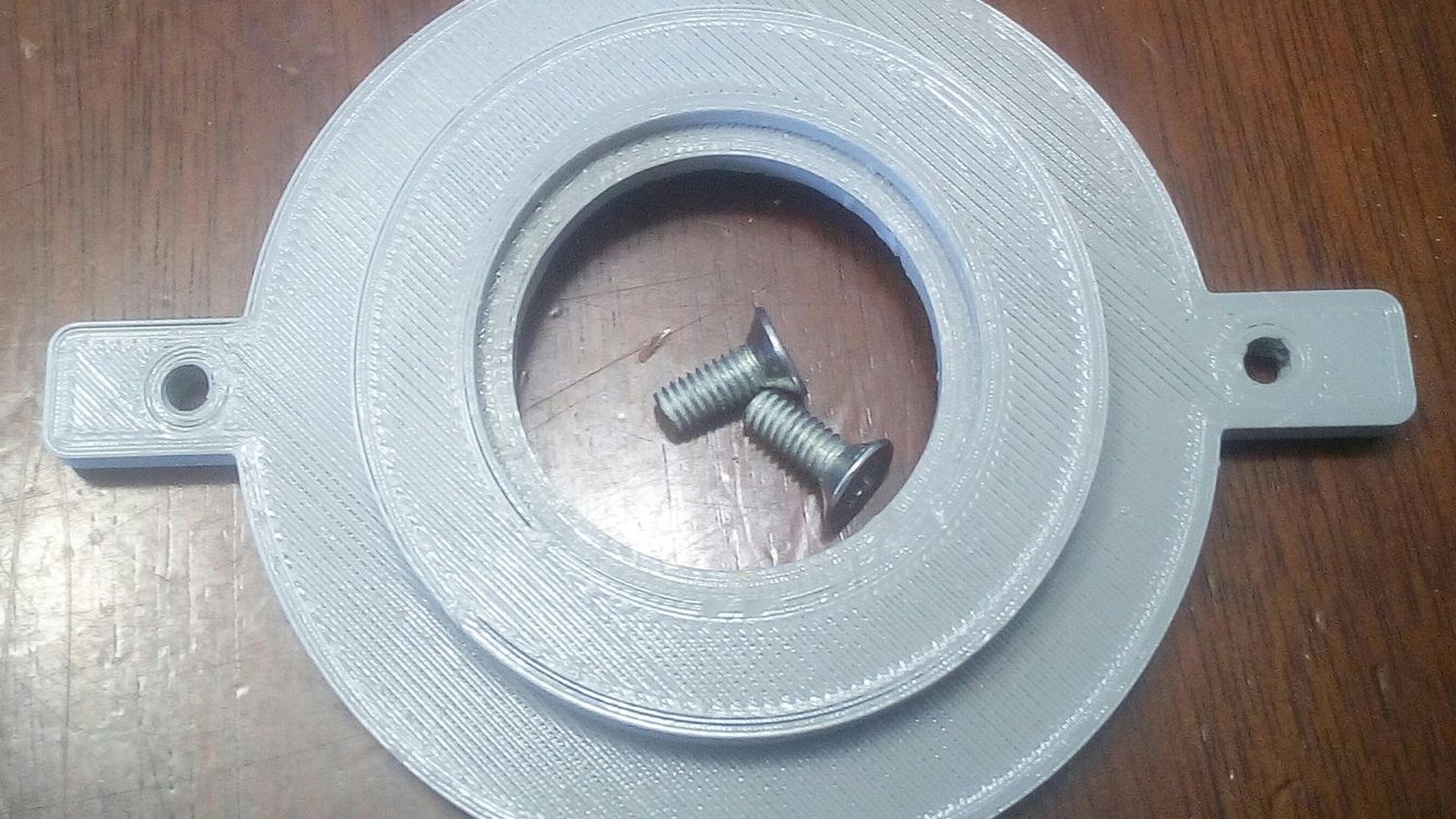
Die meisten Betriebsmittel in der Fertigung sind Einzelstücke, die mindestens einmal überarbeitet werden. Eine gefräste Vorrichtung bindet Programmierung, Aufspannung und Maschinenzeit für etwas, das nach der ersten Schicht ohnehin geändert wird. Deshalb haben sich gedruckte Vorrichtungen in der Produktion deutlich früher durchgesetzt als gedruckte Endanwendungsteile.
Wo gedruckte Vorrichtungen funktionieren und wo nicht
Gedruckte Betriebsmittel sind zuverlässig beim Positionieren, Halten, Führen und Prüfen. Ungeeignet sind sie dort, wo Späne und Kühlschmierstoff auf Schlagbelastung treffen, wo eine Fläche unter hohem Druck ohne Verschleißeinsatz gleitet oder wo die Vorrichtung dauerhaft oberhalb der Wärmeformbeständigkeit des Werkstoffs steht. Alles dazwischen ist eine Frage von Werkstoff und Wandaufbau, nicht des Verfahrens.
- Montagehilfen, die einen Handgriff reproduzierbar machen und Ausschuss in der Endmontage senken
- Prüfaufnahmen, die ein Bauteil für Messuhr, Kamera oder Sichtprüfung immer gleich halten
- Gut-Schlecht-Lehren, die eine langsame Messung durch eine Prüfung in zwei Sekunden ersetzen
- Greiferbacken mit formangepassten Kontaktflächen, die empfindliche Teile ohne Abdrücke greifen
- Bohr- und Frässchablonen mit eingepressten Stahlbuchsen, die das Werkzeug sauber führen
Bei Betriebsmitteln zählt Steifigkeit, nicht Festigkeit
Eine Vorrichtung fällt selten durch Bruch aus. Sie fällt aus, weil sie sich durchbiegt, verzieht oder kriecht und das aufgenommene Bauteil dadurch einige Zehntel daneben liegt. Entscheidend sind deshalb Steifigkeit und Maßhaltigkeit. PA12-CF ist unsere Standardwahl, weil es steif, maßstabil und verschleißfest ist. PC ist die Antwort, wenn Wärme im Spiel ist, etwa neben einem Ofen oder einer Heißnietstation. ASA hält Witterung und UV-Strahlung aus. Reines ABS reicht für leichte Montagehilfen, bei denen Kosten wichtiger sind als Steifigkeit.
Konstruktionsregeln, die eine Vorrichtung brauchbar halten
- Gewindeeinsätze überall dort setzen, wo eine Schraube mehr als ein paar Mal gelöst wird
- Eingepresste Stahl- oder Messingbuchsen an Bohrführungen und Drehpunkten verwenden, keine gedruckten Bohrungen
- Aufnahmeflächen mit definiertem Spiel auslegen, meist 0,1 bis 0,2 mm, und die Bezugsflächen kennzeichnen
- Die Unterseite verrippen statt die Wände zu verdicken, damit die Vorrichtung ohne lange Druckzeit steif bleibt
- Möglichst so drucken, dass die Last nicht senkrecht zu den Schichten wirkt, denn die Schichthaftung ist die schwache Achse
- Teilenummer und Revision sichtbar eingravieren, sonst werden zwei ähnliche Vorrichtungen an der Werkbank verwechselt
Was eine Vorrichtung tatsächlich kostet
Interessant ist nicht der Preis der ersten Vorrichtung, sondern der Preis der zweiten Version. Beim Fräsen fallen Programmierung und Rüsten erneut an. Beim Druck kosten Material und Maschinenzeit erneut, sonst nichts. Teams, die Betriebsmittel als Verbrauchsgut und nicht als Investition behandeln, haben am Ende meist die besseren Vorrichtungen, weil niemand eine schlechte Konstruktion verteidigt, um versunkene Kosten zu rechtfertigen.
Senden Sie uns die STEP-Datei des Werkstücks, nicht nur die der Vorrichtung. Der Großteil der Vorrichtungsgeometrie ergibt sich aus dem Bauteil, das sie aufnehmen soll, und wir können Probleme mit Spiel und Zugänglichkeit melden, bevor etwas gedruckt wird.