
FDM-Toleranzen: Welche Genauigkeit im 3D-Druck realistisch ist
Realistische Maßtoleranzen für FDM-Bauteile, woher Abweichungen kommen, wie sich Bohrungen und Wellen verhalten und wie Sie Passungen angeben, die beim ersten Druck sitzen.
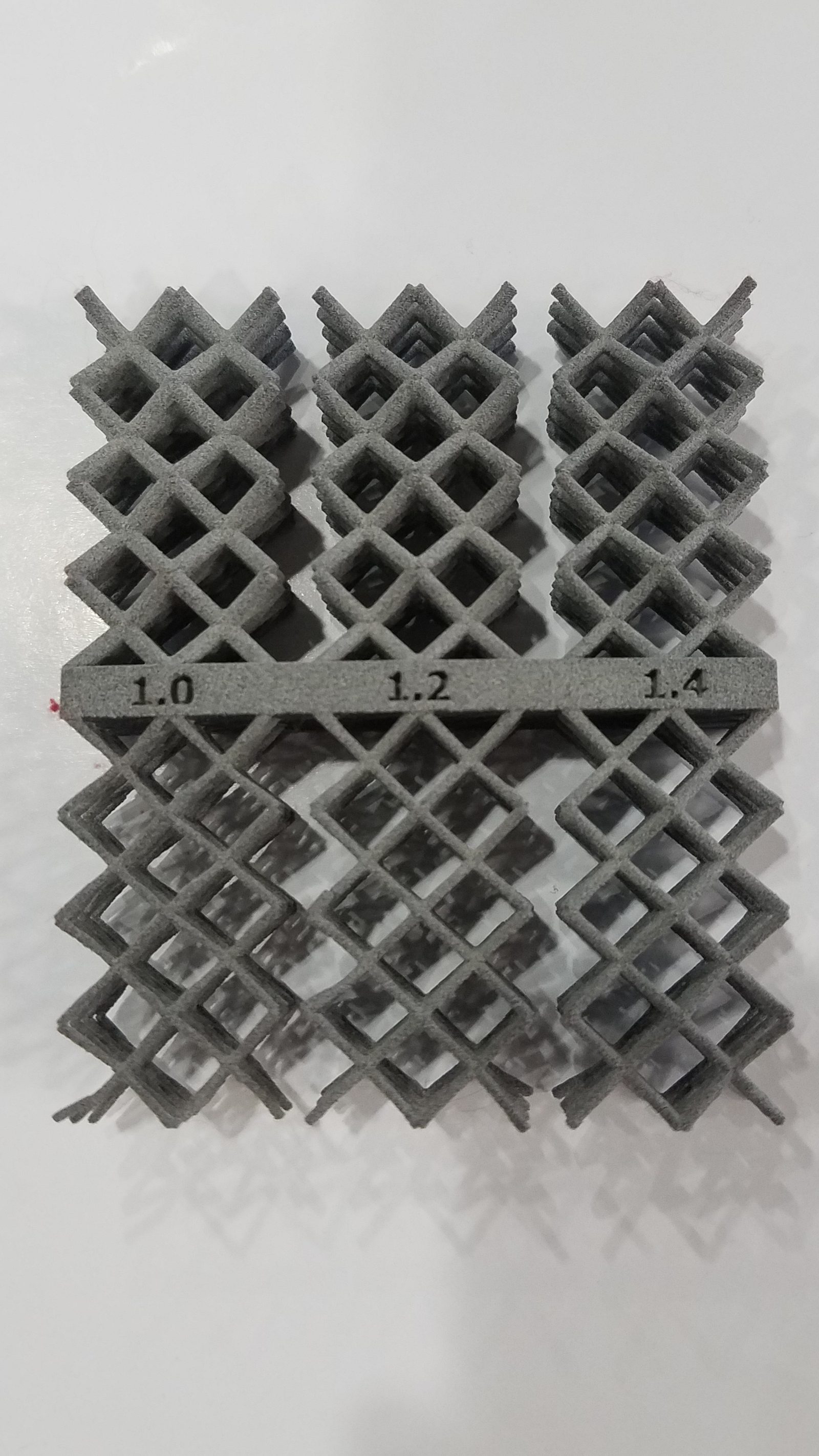
Im Einkauf wird regelmäßig gefragt, welche Toleranz wir einhalten. Ehrlich beantwortet lässt sich das nicht mit einer einzelnen Maschinenangabe, denn die erreichbare Toleranz im FDM hängt vom Werkstoff, von der Bauteilgröße, von der Geometrie und von der Orientierung im Bauraum ab. Was wir Ihnen nennen können, sind die Bereiche, mit denen wir unsere Fertigung planen, und die Konstruktionsentscheidungen, die ein Bauteil zuverlässig innerhalb dieser Bereiche halten.
Die Bereiche, mit denen wir planen
- Maßstabile Werkstoffe wie PLA, PETG und die carbonverstärkten Typen: etwa ±0,2 mm bei kleinen Merkmalen oder ±0,2 Prozent des Nennmaßes über 100 mm, je nachdem, welcher Wert größer ist
- Schwindende Werkstoffe wie ABS, ASA und PC: eher ±0,3 mm oder ±0,3 Prozent, mit größerer Abweichung an langen flachen Abschnitten
- Unverstärktes PA12 und PA6 haben den größten Streubereich, weil diese Werkstoffe Feuchtigkeit aufnehmen und nach dem Druck maßlich weiterarbeiten
- Am wiederholgenauesten ist in der Regel die Z-Höhe, während Merkmale in der Ebene stärker auf Schwindung und Abkühlung reagieren
Woher Abweichungen tatsächlich kommen
In der Praxis sind vier Effekte dafür verantwortlich. Erstens die Schwindung beim Abkühlen, die mit der Länge des Bauteils zunimmt. Zweitens die Extrusionsbreite, die jede Bahn etwas breiter macht als die Nennwand und Bohrungen dadurch zu klein ausfallen lässt. Drittens der thermische Verzug auf großen ebenen Flächen, der die Ecken anhebt und die Ebenheit verändert, statt ein einzelnes Maß zu verschieben. Und viertens der Elefantenfuß in den ersten Schichten, bei dem die Anpressung die Basis leicht verbreitert. Keiner dieser Effekte ist zufällig. Genau deshalb liefert dieselbe Datei mit demselben Profil von Charge zu Charge sehr ähnliche Ergebnisse.
Bohrungen werden kleiner, und zwar vorhersehbar
Eine senkrechte Bohrung fällt im FDM grundsätzlich zu klein aus, weil der Kreis aus geraden Segmenten angenähert wird und die Bahn dabei leicht nach innen wandert. Bei einer Bohrung von 5 mm fehlen je nach Werkstoff häufig 0,1 bis 0,3 mm. Wenn eine Bohrung eine Schraube, ein Lager oder einen Stift aufnehmen muss, konstruieren Sie sie einfach auf Nennmaß. Wir kompensieren das entweder im Druckprofil oder sehen Aufmaß vor und reiben die Bohrung nach dem Druck auf. Das Aufreiben geht schnell und liefert ein deutlich besseres Ergebnis, als ein Übermaß in der Konstruktion zu schätzen.
Passungen mit Spiel konstruieren, nicht über Toleranzketten
- Leichtgängiges Spiel zwischen zwei gedruckten Teilen: 0,3 bis 0,5 mm gesamt
- Gleitpassung, die geführt wirken soll: 0,15 bis 0,25 mm
- Presspassung eines gedruckten Stifts in einer gedruckten Bohrung: 0,05 bis 0,1 mm Übermaß, wobei man mit einer Anpassungsrunde rechnen sollte
- Schraubverbindungen: einen Gewindeeinsatz oder eine Messingbuchse statt eines gedruckten Gewindes verwenden, sobald die Verbindung mehrfach geöffnet wird
Nennen Sie die kritischen Maße
Das Nützlichste, das Sie mit einer Datei senden können, ist eine Zeichnung oder ein kurzer Hinweis mit den zwei oder drei Maßen, die stimmen müssen. Das verändert die Orientierung im Bauraum, welche Flächen auf der Platte liegen, ob wir Aufmaß vorsehen und was wir am Erstteil messen. Ein Bauteil mit drei kritischen Maßen ist unproblematisch. Ein Bauteil, bei dem alles kritisch ist, gehört meist in die zerspanende Fertigung, und das sagen wir Ihnen auch.
Wie wir Toleranzen über die Serie stabil halten
- Ein dokumentierter Parametersatz pro Bauteil, der nach der Erstteilfreigabe gesperrt wird
- Getrocknetes Filament aus einer kontrollierten Charge, weil Feuchtigkeit die Extrusion und damit die Maße verändert
- Die gleiche Orientierung und die gleiche Position auf der Bauplatte bei jedem Wiederholauftrag
- Eine Maßprüfung der markierten kritischen Merkmale, deren Ergebnisse pro Charge dokumentiert werden
Wenn bei einem Bauteil schon einmal eine Passung nicht gesessen hat, senden Sie die Geometrie und das kritische Maß. Meist liegt die Lösung in der Orientierung, im Spiel oder in einer nachgeriebenen Bohrung, nicht in einem anderen Lieferanten.